Well i guess most of you are familiar with that there´s thing known as tube testers. Seing this is GAB...yea well. Most of these testers are old...rarely calibrated and what not. Yes,i´ve got one of them too. A old East-German made RPG-70.
That RPG of mine i´ve overhauled from one end to the other and indeed...it hands me the most basic information.

Many come down on these East-German builds as being ripoffs of the old West-German Funke builds but...nah. Off mark. No matter they do what they claim to do and done deal. Mine is a later build,being put together back in 1977. For a regular tube tester that´s "new".
Anyways.
What when we´re in need of more information and what´s more...what about making the whole concept hit the 21st century?
Well.
Enter U-Tracer.
http://www.dos4ever.com/uTracer3/uTracer3_pag0.html
That´s the URL for them.


The U-Tracer is delivered in kit form. A mere 215 Euros does it and...that makes for that some regard this as a toy. Having completed my own i can only attest to that it is CERTAINLY not.


Actual PCB is out of fibreglass and sturdy to the build. Through plated as far as the holes. In short a piece of well engineered PCB.


...various components come neatly packaged and marked.
Altho this to a large extent comes down to "paint by numbers" i still want to go on record and state that a U-Tracer is NOT a kit for the novice. You need some basic understanding before taking on a build like this.

To handle this...one SERIOUSLY well written build manual!

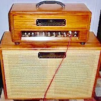
As it indeed is a kit that means that you´ll have to look up various bits n pieces on your own. This little pine box i picked up locally. Added some hinges and a latch..you get the drill.
So. I took to trying to figure this project out. One of the major issues with tube testers/tracers is the sockets. Tubes have been produced with different sockets and pinouts out the fabled so..how to handle that?
Well.


Me i´m a lazy SOB. Most engineers are...that´s why we become..
 So what i did was opt to order quite a few so called saver sockets for octals and novals directly from Asia. They´re cheap enough.
So. To NOT end up with a build that´s filled to the brim with various sockets i decided on going this route..and it´ll be simple enough to repin these saver sockets within to cater to whatever tube i wish to test really.
This entails even using old odd sockets...like for EL-12´s..EF-12s..and what not. ECL-82 and 86...ECC-808´s...you name it. The saver sockets will in short just do what i ask of them.

One of the few limitations of the U-Tracer is that it´s limited to 1.5A for heater current. So. I opted to install a separate transformer for that,so i can switch between the internal and external (read-transformer) heaters.
The actual U-Tracer in turn is powered by a common laptop brick. As a brick like that is switched that brings that the capacity of it,in amperes,is rather large.

That there in turn is what that external transformer will head into. A PWM (pulse width modulated) piece of kit that makes it possible to control output voltage between 2VDC and approx 35VDC.

The actual build then..IS very much "paint by numbers". The designers of the kit have very wisely made it a point to halt every now and then to test that the various "blocks" of the build works as intended.
For some reason the designers recomend that you use a very sharp edged/thin tip for your soldering station. I for one found this NOT to be true. Working on tube stuff the tips i use are rather large...and i got by real easy with my regular "medium" tip and 1mm dia solder.

Faceplate. A simple anodized piece of 2mm thick aluminium.

I went at it..and all of a sudden i was done. Or..so i thought.

...i had missed out on a pair of resistors (omitted them completely). An error that was remedied in no time tho so no harm no foul.

Flipside of the faceplate and...OH will this side of it every get busy!

Of course the mains switch needed a "Racing" touch!


To keep control of the lid i opted to install a regular gas spring for kitchen doors.

Pilot light. Of course.

Then for a digital voltmeter and a trim pot for that PWM PCB,to be able to adjust output voltage.

The miniswitch is to choose between heater voltage from the stand alone transformer or the onboard heater circuit of the U-Tracer.

Wiring then. DAMN i hate laying heater wiring down!

A 10A rectifier and an e-cap for the standalone unit.

That pine box got some mahogony taint. Tried using clearcoat within but..that simply got to shiny for my taste. It´s a damn tool after all,so i opted to go with regular oil instead.

Yes. Of course that mains breaker needed a "remove before flight"


Starting to give you an idea i guess.

A´la the well known AVO testers loads of ferrites were added for the wiring.

Sure enough. An old EL-84 being put through its paces...