GRIMESPACE wrote:ironman28 wrote:Just picked up a used JCA50. Been lurking here for the last couple of months watching things progress.
Fired it up last night into a 2-12 celestion cab.Not sounding too good at this point, still has the original Chinese pres in it. The previous owner installed a set of JJs for the PA. Gonna start swapping the pres out to see what kind of improvement I get.
Some observations:The OT is huge compared to most 50W amps. I don't know if this reflects a design philosophy with a full band width OT or was it a mfg decision.
Any way once the tubes are upgraded I will start to tweak it. In no particular order;
The FX loop is not very flexible. Kind of a 80's design
Seems to be a well constructed PCB design with a sturdy chassis that lends itself to modding (that's why I'm here)
Clean up the crunch channel
Move the FX to post MV (like the 22)
Add send and return controls for the loop
Maybe change up the tone stack slope and mid shift
redo the presence circuit to be a "cut/boost" like a HIWatt
This should be fun!
BTW anyone have the JCA50 PA schematic?
Hiya - welcome to the club!
Anxious to hear what you come up with on the mods, although tubes, bias, and depth mod will give you a huge head start. The effects loop stuff is of major interest to me - I've wanted to try out impulses for recording with the send, but was disappointed to find that it's pre-EQ. That said, I'm a little fuzzy on how you'd go about implementing the effects loop post-master volume - wouldn't that potentially overpower even line-level effects?
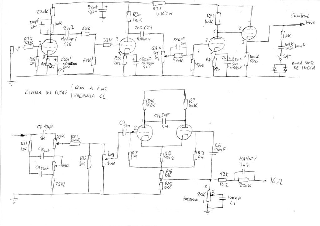
I actually created a 50H documentation thread over in DIY some time ago, but just realized that I never posted the schematics. That's been fixed as of a couple minutes ago. I've made links to relevant stuff (like my 50H documentation thread) on the 3rd post in this thread, but here's the shortcut anyway: JCA50H Documentation
Thanks for the welcome!
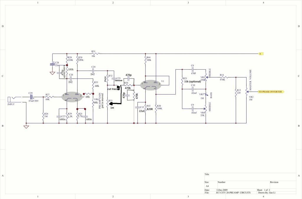
If you look at the loop placement in the JCA22 schematic you will see how a post MV loop circuit would work. I think the JCA22 loop works better for most players because of the signal losses in the tone stack and MV attenuation. There also seems to be some send attenuation through R29/R30.
So in essence the tone stack would be driven by V3. V4 would be freed up to perform both the send and return functions for the loop. 1/2 of V4 would be a send buffer using a cathode follower and the other 1/2 of V4 is the return buffer. From there it is easy to add send/return controls for each section. I would not use the exact circuit from the 22 as there are better loop designs. There are several kits available to add tube FX loops but that's not required here . All the basic elements can be created using V4 and the associated parts. The end result will be a transparent tube loop with send/return controls, switchable series/parallel and switchable -20/0db return.
Thanks for posting the schematic. I'll keep everyone updated as things progress. I would eventually like to create some DIY step by step instructions for the other members.
 . Perhaps Jay, käsebrot, or one of the other regulars here can offer up some input that may be of use.


