5F6A-M Bassman Micro
Posted: Sat Apr 04, 2015 10:20 am
This is my latest micro amp project, the Bassman Micro tube guitar amplifier. It's a compact, moderately easy to build, three tube, 3 to 5 watt output practice amp (around 3 watts with a 12AU7 power tube and around 5 watts with a 12BH7). The Bassman Micro's single channel preamp circuit was inspired by the 5F6A Bassman's Bright Hi channel. The Marshall JTM45 preamp is an exact copy except for the use of a 12AX7 in V1 so this amp could also be called the JTM45 Micro. The Bassman Micro features two stages of gain, a tone stack buffer, a cathodyne phase inverter and a true push-pull power amp.
More inof on the Bassman Micro: http://robrobinette.com/Bassman_Micro.htm
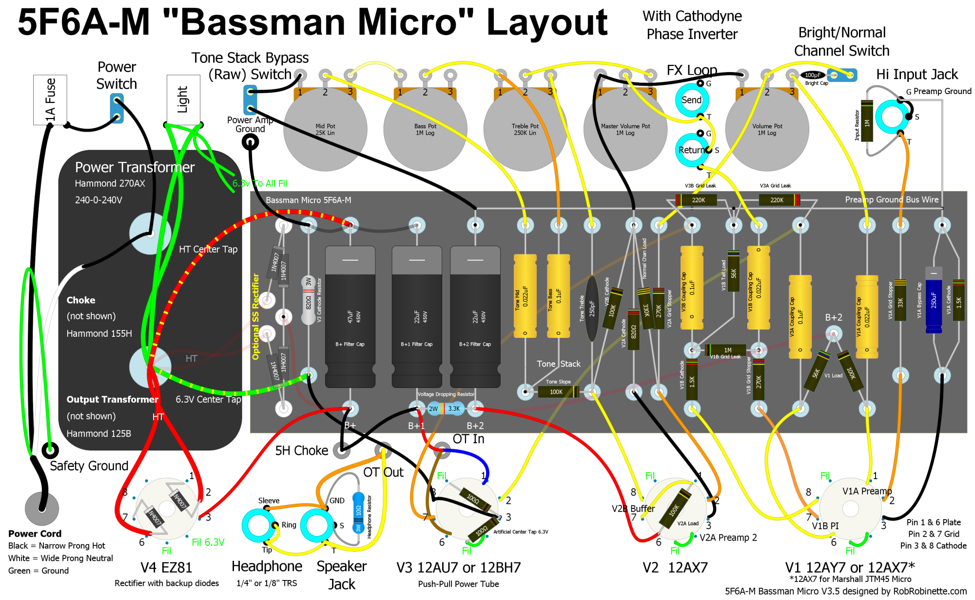
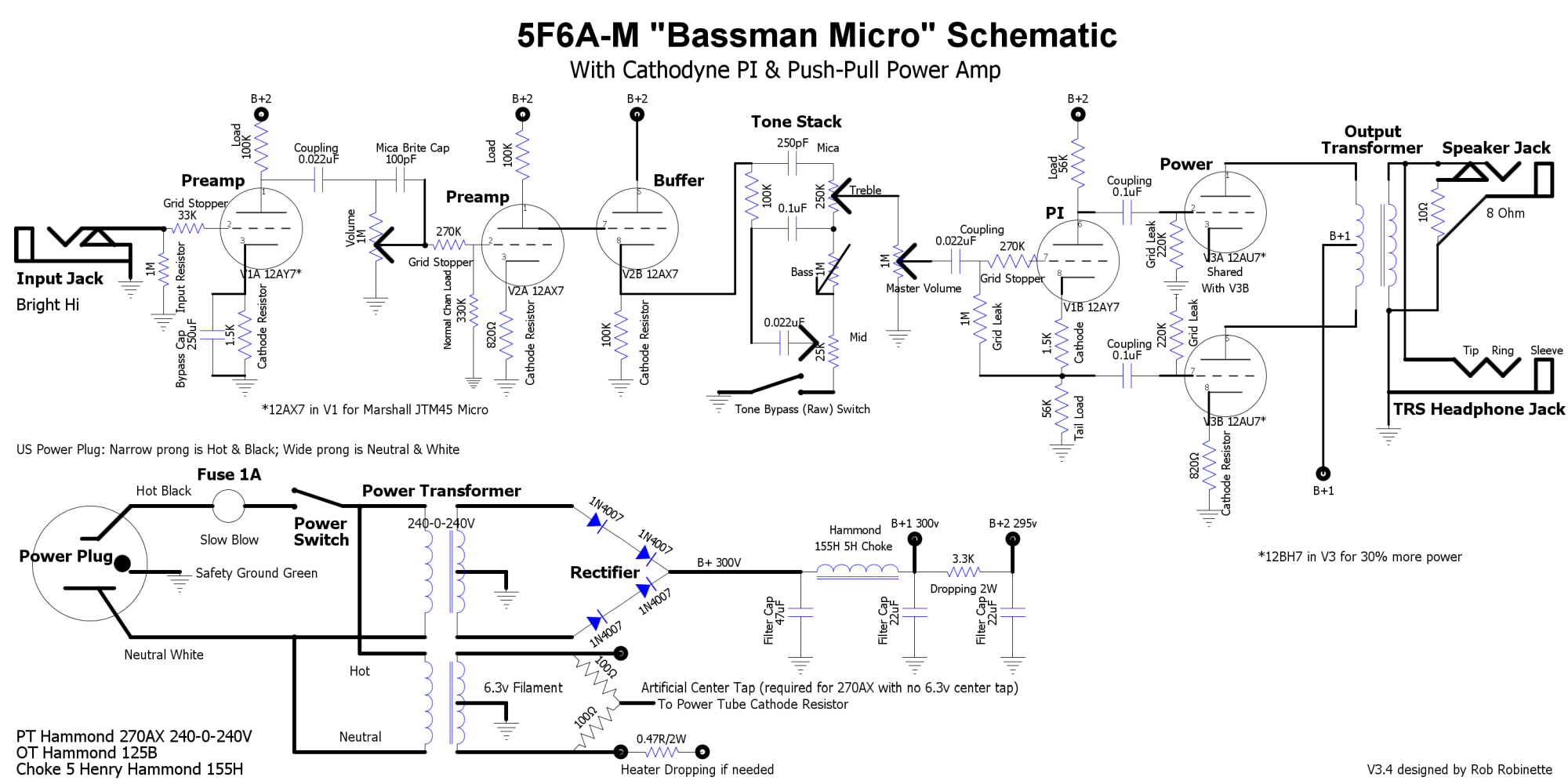
I'm a big fan of the 1950's Fender tweed amps and the 5F6A Bassman is a legendary amp that was copied by Marshall and became the foundation of that company's amp lineup so I decided design a Micro version of the Bassman. I used an almost exact copy of the Bassman's preamp and paired it with a cathodyne phase inverter and small bottle push-pull power amp. Why a cathodyne PI? Because I didn't need the extra gain of the Bassman's long tail pair phase inverter and the it would have required another tube. The greatest weakness of the cathodyne PI is if driven too hard it can develop nasty double-frequency distortion. I use a pre-phase inverter master volume paired with a 270k phase inverter grid stopper resistor to eliminate double-frequency distortion.
I liked the output and flexibility of the 12AU7/12BH7 tubes for the true push-pull power amp. The 12AU7 with both triodes in push-pull will develop around 3 to 4 watts of output power. Swap in a 12BH7 and the output increases to 4 to 5 watts. My H&K Tubemeister 5 uses a 12BH7 in push-pull and it sounds very good. The 12AU7 and 12BH7 tubes are very similar in output tone but the volume boost from the 12BH7 is noticeable. Both tube types are readily available with the 12BH7 going for about $5 more than a 12AU7.
One of the reasons I chose to use the Fender 5F6A tweed Bassman preamp in this project is the Marshall JTM45 uses an exact copy of the circuit except Marshall calls for a 12AX7 in V1 instead of the Bassman's lower gain 12AY7. All that's required to convert the Bassman Micro into a JTM45 Micro is to put a 12AX7 in V1. A 12AX7 in V1 gives you much more overdrive and pushes the Bassman Micro's tone into the 1960's.
I installed the Bright/Normal Channel Switch because the only difference between a 5F6A's channels is the Bright Cap. By putting it on a switch you can choose between the two Bright and Normal channels.
The Negative Feedback Switch allows you to disconnect the feedback loop and get a grittier, more 5E3 Deluxe type tone with earlier breakup, or turn on the feedback for the standard Bassman tone. I went with a 82k feedback resistor because the 5F6A used a 27k resistor with a 2 ohm speaker tap. To get the equivalent feedback from my 8 ohm speaker tap the resistor must be bumped up to 56k. Use a 39k resistor for a 4 ohm speaker tap and 82k for a 16 ohm tap. Feel free to adjust the feedback resistor value to your liking or even install a pot to vary the feedback but I'd use about 12k as the minimum feedback resistance (12k resistor in series with a 100k pot).
The Tone Stack Bypass Switch is an easy mod that removes the signal sucking tone stack from the circuit. The signal will be 'boosted' when the tone stack is bypassed.
The EZ81 rectifier tube uses a standard 9-pin socket and 6.3V filament heat so no 5V power transformer output is needed. If your power transformer does have 5V available and you'd rather use a standard, full size 8 pin rectifier tube like a 5Y3GT then just wire the 8 pin socket with the HT to pins 4 and 6, 5V heater lines to 2 and 8 and the B+ power line to pin 8.
More inof on the Bassman Micro: http://robrobinette.com/Bassman_Micro.htm
I'm a big fan of the 1950's Fender tweed amps and the 5F6A Bassman is a legendary amp that was copied by Marshall and became the foundation of that company's amp lineup so I decided design a Micro version of the Bassman. I used an almost exact copy of the Bassman's preamp and paired it with a cathodyne phase inverter and small bottle push-pull power amp. Why a cathodyne PI? Because I didn't need the extra gain of the Bassman's long tail pair phase inverter and the it would have required another tube. The greatest weakness of the cathodyne PI is if driven too hard it can develop nasty double-frequency distortion. I use a pre-phase inverter master volume paired with a 270k phase inverter grid stopper resistor to eliminate double-frequency distortion.
I liked the output and flexibility of the 12AU7/12BH7 tubes for the true push-pull power amp. The 12AU7 with both triodes in push-pull will develop around 3 to 4 watts of output power. Swap in a 12BH7 and the output increases to 4 to 5 watts. My H&K Tubemeister 5 uses a 12BH7 in push-pull and it sounds very good. The 12AU7 and 12BH7 tubes are very similar in output tone but the volume boost from the 12BH7 is noticeable. Both tube types are readily available with the 12BH7 going for about $5 more than a 12AU7.
One of the reasons I chose to use the Fender 5F6A tweed Bassman preamp in this project is the Marshall JTM45 uses an exact copy of the circuit except Marshall calls for a 12AX7 in V1 instead of the Bassman's lower gain 12AY7. All that's required to convert the Bassman Micro into a JTM45 Micro is to put a 12AX7 in V1. A 12AX7 in V1 gives you much more overdrive and pushes the Bassman Micro's tone into the 1960's.
I installed the Bright/Normal Channel Switch because the only difference between a 5F6A's channels is the Bright Cap. By putting it on a switch you can choose between the two Bright and Normal channels.
The Negative Feedback Switch allows you to disconnect the feedback loop and get a grittier, more 5E3 Deluxe type tone with earlier breakup, or turn on the feedback for the standard Bassman tone. I went with a 82k feedback resistor because the 5F6A used a 27k resistor with a 2 ohm speaker tap. To get the equivalent feedback from my 8 ohm speaker tap the resistor must be bumped up to 56k. Use a 39k resistor for a 4 ohm speaker tap and 82k for a 16 ohm tap. Feel free to adjust the feedback resistor value to your liking or even install a pot to vary the feedback but I'd use about 12k as the minimum feedback resistance (12k resistor in series with a 100k pot).
The Tone Stack Bypass Switch is an easy mod that removes the signal sucking tone stack from the circuit. The signal will be 'boosted' when the tone stack is bypassed.
The EZ81 rectifier tube uses a standard 9-pin socket and 6.3V filament heat so no 5V power transformer output is needed. If your power transformer does have 5V available and you'd rather use a standard, full size 8 pin rectifier tube like a 5Y3GT then just wire the 8 pin socket with the HT to pins 4 and 6, 5V heater lines to 2 and 8 and the B+ power line to pin 8.
